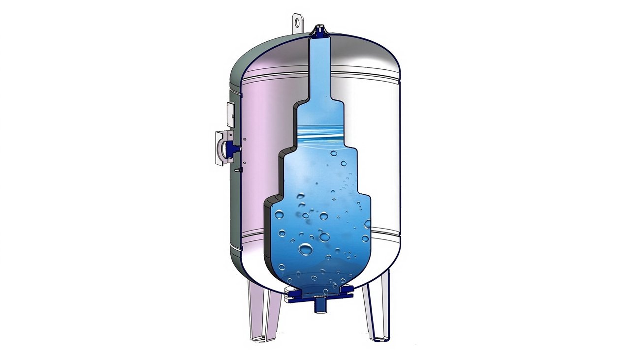
A leaking water pump pressure tank degrades your entire domestic water system, causing pump short-cycling, rapid contactor wear, and destructive water hammer. In a healthy hydropneumatic system, a butyl rubber or EPDM bladder separates pressurized air from stored well water. When a leak develops, the issue usually stems from one of two sources: an external pinhole leak caused by flange corrosion or weld rot, or an internal bladder rupture that floods the pneumatic chamber with water. Once water displaces the captive air charge, water's incompressibility forces the pump to cycle on and off within seconds of opening any fixture. Left unaddressed, this cycling burns out 230V single-phase pump motors and melts mechanical pressure switch contacts. Diagnosing and rebuilding the pressure tank requires isolating hydraulic circuits, depressurizing pneumatic reservoirs, and evaluating mechanical joints. In this comprehensive engineering guide, I break down the physical teardown, bladder replacement, seal re-seating, and pressure re-calibration process to bring your well system back to factory specifications.
Anatomy and Failure Modes of Captive Air Pressure Tanks
To repair a pressure tank effectively, you must understand its internal cross-section. A standard pre-charged pressure vessel features a domed carbon-steel or composite outer shell with an internal bladder anchored at the top diffuser or bottom discharge flange. The upper volume contains compressed air, charged via a standard brass Schrader valve threaded 0.305-32 UNEF at the dome apex. The lower volume connects to the 1-inch or 1.25-inch NPT discharge pipe leading directly to the building plumbing and pressure switch.
Two primary mechanical failures generate visible leaks. The first is galvanic or crevice corrosion at the bottom retaining flange. Water pump tanks operate in high-humidity basements or unconditioned well pits. Condensation drips down the outer wall and pools beneath the bottom retaining ring, corroding the zinc-plated carbon steel bolts. The gasket seal fails, allowing water to weep along the bottom perimeter.
Internal bladder degradation represents the second failure mode. Repeated cycling causes mechanical fatigue, flexing the elastomer millions of times against rough interior wall welds. Eventually, the rubber tears. Pressurized air escapes into the water stream, discharging through household faucets as milky aerated water. Simultaneously, water fills the pneumatic void, soaking the tank wall and rising directly to the top Schrader valve. If pressing the valve pin ejects water instead of dry air, the bladder has completely compromised the air-over-water barrier.
Diagnostic Verification and Pre-Repair Testing
Before ordering parts or turning a wrench, verify the exact failure mechanism using mechanical testing. Cut power to the well pump at the dedicated 2-pole 20A or 30A circuit breaker. Lock and tag the breaker panel. Connect an analog 0-100 PSI liquid-filled pressure gauge to the boiler drain valve located on the tank tee. Open a nearby garden hose or utility sink to relieve static line pressure completely until the gauge reads 0 PSI.
Remove the protective cap from the Schrader valve on the tank dome. Depress the central valve core pin using an insulated screwdriver tip for two seconds. If an aerosol spray or continuous stream of liquid exits, the internal bladder is torn. If dry air hisses out, measure the pre-charge pressure with a calibrated pencil or digital pressure gauge. Standard factory pre-charge is typically 28 PSI or 38 PSI, matching standard 30/50 PSI or 40/60 PSI pressure switch differentials. If the reading is 0 PSI without water, the valve core or the bladder membrane has failed slowly over time.
Next, perform a physical weight check. Gently rock the tank along its vertical axis. An empty 44-gallon tank with an intact bladder weighs approximately 45 to 55 lbs when isolated and drained. If the tank feels extraordinarily heavy—weighing upwards of 200 to 300 lbs—the air chamber is flooded. Water is trapped above the deflated membrane, unable to escape through the lower discharge port due to hydrostatic sealing.
Disassembly and Water Evacuation Procedure
Draining a waterlogged tank requires controlled venting because the weight of the water creates a vacuum when draining from the bottom port. Keep the drain valve open at the tank tee and run a 3/4-inch braided garden hose to an exterior floor drain. If the bladder is intact but the bottom flange is leaking, line water will discharge freely under residual air pressure. If the bladder is burst, water will stop flowing once gravity pressure equalizes.
To break the hydraulic vacuum inside a waterlogged vessel, remove the Schrader valve core using a four-way tire valve tool. Thread a 1/4-inch NPT air compressor fitting into the port and apply 10 to 15 PSI of regulated compressed air. This forces the trapped water volume out through the bottom drain. Maintain air pressure below 30 PSI to prevent violently blowing out weakened rubber remnants through the plumbing tee.
Once the water is completely evacuated, disconnect the structural piping. Use two 14-inch pipe wrenches to loosen the union or female NPT adapter connecting the tank base to the main brass tank tee. Apply counter-torque to prevent twisting the manifold or snapping the schedule 40 brass nipple. Unbolt the tank hold-down brackets from the concrete pad. Carefully tilt the empty tank horizontally onto sawhorses lined with rubber mats to prevent scratching the exterior protective epoxy coating.
Bottom Flange Teardown and Bladder Replacement
With the tank secured horizontally, inspect the bottom retaining flange. In modern captive-air tanks like the cutaway design, the bladder neck forms the mechanical seal between the curved tank throat and the bolted steel retention plate. Using a 1/2-inch or 9/16-inch socket on a 3/8-inch drive ratchet, back out the perimeter retaining bolts in a star pattern to avoid warping the flange plate.
Remove the steel flange assembly and examine the mating surface. Deep pitting, scale, and rust deposits along the sealing bead prevent a watertight joint. Scrape the surface flat with a hardened steel gasket scraper, followed by wet sanding with 220-grit silicon carbide sandpaper. Degrease the metal with isopropyl alcohol. If the flange shows corrosion deeper than 0.8 mm, replace the flange with a 304 stainless-steel aftermarket equivalent.
Reach into the throat and extract the old EPDM bladder. If the tank utilizes an upper stabilization stem (as visible in tall commercial tanks), unthread the top retaining nut beneath the Schrader fitting dome before pulling the bladder free. Fold the new replacement bladder lengthwise, dust the exterior with food-grade talc powder to prevent chafing against the dry tank walls, and feed it through the lower neck opening. Thread the upper alignment stem through the top dome hole, torque the upper retaining locknut to 18 ft-lbs (24.4 Nm), and smooth out any internal twists. Seat the molded rubber bead cleanly over the throat rim.
Reassembly, Torque Specifications, and Leak Testing
Reinstall the lower retaining flange over the aligned rubber bead. Thread the zinc-plated or 316 stainless-steel Grade 5 fasteners in by hand. Never rely on an impact driver here; uneven clamping shears the elastomer and introduces pinhole leaks at the bolt hole edges. Use a calibrated click-type torque wrench to tighten the bolts in three distinct criss-cross passes: first to 10 ft-lbs (13.6 Nm), second to 20 ft-lbs (27.1 Nm), and a final pass to 28 ft-lbs (38.0 Nm).
Step-by-Step Tightening Sequence:
[1] Pass 1: 10 ft-lbs
[6] [3] Pass 2: 20 ft-lbs
[4] [5] Pass 3: 28 ft-lbs (Final)
[2]
Reinstall the Schrader valve core with 3 to 5 in-lbs of torque. Connect an oil-free air compressor to the Schrader valve and pressurize the empty tank to exactly 2.0 PSI below your well pump's cut-in threshold. For a standard 40/60 PSI pressure switch, charge the dry bladder chamber to exactly 38.0 PSI (2.62 bar). For a 30/50 switch, charge it to 28.0 PSI (1.93 bar). Check the valve stem with a 50/50 solution of laboratory leak detection fluid or soapy water to confirm zero bubble formation over 10 minutes.
Reconnect the tank to the plumbing manifold using fresh PTFE paste (thread sealant) and two wraps of high-density PTFE tape applied clockwise on the 1-inch NPT male threads. Thread the union together and snug it using two pipe wrenches until the mechanical stop aligns. Close the boiler drain valve.
| Inspection Metric | Defective / Ruptured | Post-Repair Value | Acceptance Standard |
| :--- | :--- | :--- | :--- |
| Air Pre-Charge Pressure | 0.0 to 12.5 PSI | 38.0 PSI (for 40/60 setup) | Target Cut-in - 2 PSI |
| Flange Bolt Clamping Torque | Uneven (< 8.0 ft-lbs) | 28.0 ft-lbs | ±1.0 ft-lbs uniform |
| Cycle Frequency (5 gpm draw) | Every 8 to 12 seconds | 90 to 120 seconds | Minimum 60 seconds |
| Schrader Valve Leak Rate | Continuous bubbles | 0 bubbles over 15 min | Helium/Soap leak tight |
| Tank Shell Weight (Drained) | 215 lbs (waterlogged) | 48.5 lbs | Spec ± 3.0 lbs |
Real Failure Story: Pinholes, Pinching, and Micro-Leaks
During a field rebuild of a 52-gallon Well-X-Trol tank connected to an ESP32-monitored smart well pump system, I encountered an elusive failure that highlights the danger of rushing bladder alignment. We observed rapid dropouts on our line pressure sensor—an industrial 0-5V, 0-100 PSI piezoresistive transducer polled via an ADS1115 ADC. The system exhibited 5 PSI cycling drops within 4 seconds of opening a single 2.5 GPM faucet, pointing directly to severe waterlogging.
After draining 210 pounds of trapped water and replacing the internal bladder, I torqued the bottom flange straight to the final 28 ft-lbs specification without working through intermediate stages. I recharged the pneumatic chamber to 38 PSI, reconnected the 1-inch plumbing line, and brought the well pump back online. Within 48 hours, the pressure transducer data revealed the exact same short-cycling signature. The Schrader valve sprayed pure water when tested.
Teardown revealed what broke: the newly installed EPDM bladder had pinched beneath the heavy steel ring flange during the rapid single-stage torquing. Under 55 PSI of hydraulic line pressure, the compressed rubber tore clean along the perimeter pinch point. A microscopic 1.2 mm split opened directly adjacent to bolt position 4.
I resolved the issue by rebuilding the system with a fresh bladder. This time, I applied a thin layer of food-grade silicone grease to both sides of the elastomer bead, seated the ring perfectly flush, and tightened the fasteners in three strict passes (10, 20, and 28 ft-lbs). I then performed a 24-hour pneumatic dry hold test at 40 PSI before letting a drop of water into the tank. The dry pressure held rock solid at 40.0 PSI, confirming zero leakage before final commissioning.
Conclusion
Diagnosing and repairing a leaking water pump pressure tank restores steady hydraulic delivery and protects your well pump motor from premature burnout. Understanding the distinction between replaceable-bladder vessels and permanently sealed diaphragm tanks saves critical diagnostic time. By strictly adhering to intermediate torque sequences, verifying flange flatness, and establishing the exact pre-charge differential (cut-in minus 2 PSI), you eliminate the pinches and micro-leaks that ruin premature rebuilds. Routine biannual inspections of your tank's air volume and electrical contact points will guarantee dependable operation, consistent line pressure, and years of trouble-free water service for your home or facility.
Sources
- Amtrol Engineering Data & Installation Guidelines: https://www.amtrol.com/resources/technical-documents/
- Water Systems Council - Pressure Tank Sizing & Maintenance: https://www.watersystemscouncil.org/water-well-help/well-care-info-sheets/
- Grundfos Pressure Vessel Calibration Technical Handbook: https://www.grundfos.com/resources/technical-data
- Pentair Water Pressure Tank Manuals and Technical Documentation: https://www.pentair.com/en-us/products/residential-water-supply/pressure-tanks.html
Comments