A washing machine failing to evacuate water typically halts mid-cycle and flags an error code, such as E18 on Bosch/Siemens, OE on LG, or 5E/nd on Samsung units. This symptom stems from mechanical obstructions within the hydraulic discharge path, electromechanical breakdown of the synchronous pump motor, or instrumentation drift in the hydrostatic level sensor. When the central microcontroller on the main control board initiates the drain routine, it energizes a shaded-pole or permanent magnet synchronous motor (PMSM) rated between 30W and 85W via an onboard triac or relay. If the analog water-level transducer or mechanical microswitch fails to register an empty tub within a hardcoded firmware timeout (typically 4 to 8 minutes), the control logic aborts operation to prevent pump overheating and motor driver burnout. Restoring function requires isolating mains power, safely de-watering the drum, auditing the lint trap housing, verifying winding impedance, and confirming sensory feedback across the low-voltage control loop.
Safety Protocol and Manual Water Extraction
Before undertaking physical disassembly or diagnostic measurements, disconnect the washing machine from the 120V or 230V AC mains outlet. A drum loaded with 40 to 60 liters of trapped wash liquor represents significant hydrostatic mass and an imminent flooding hazard. Locate the service access cowl positioned at the lower right or lower left corner of the front chassis panel. Release the snap-fit cowl retaining tabs using a flathead screwdriver or nylon pry tool. Behind this access door lies the drain pump filter assembly alongside a flexible rubber emergency drain hose fitted with an end-plug.
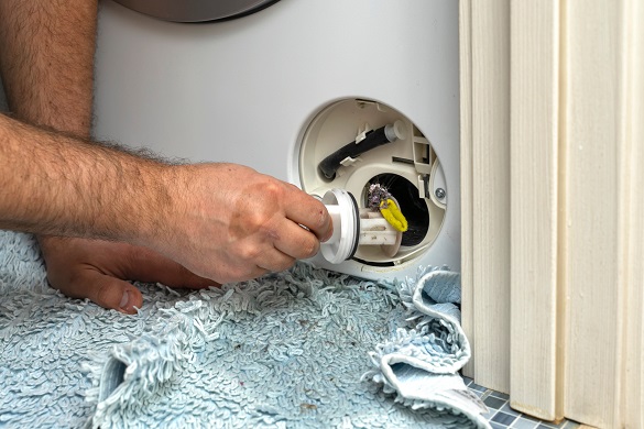
Position high-absorbency towels and a low-profile catch basin beneath the access hatch. Extract the auxiliary drain hose from its retaining clip, extend it outward, and uncap the sealing plug over your collection vessel. Allow gravity to drain the suspended water completely; expect several emptying cycles if the wash tub is full. If your chassis lacks an auxiliary drain hose, you must unthread the primary pump filter cap incrementally by counter-clockwise quarter-turns. Regulate the fluid discharge by retightening the threads as your collection pan reaches capacity.
Never completely spin the filter assembly out while water pressure remains within the tub chamber, as this will breach the perimeter gasket and flood adjacent flooring and sub-chassis electronics. Once fluid ceases exiting the auxiliary tube, recap it securely. You can now safely unscrew the coarse debris filter plug entirely to expose the internal hydraulic volute, impeller blade assembly, and chamber housing.
Inspecting and Clearing the Pump Filter Assembly
With the threaded filter plug removed, perform a tactile and optical inspection of the internal pump cavity. As captured during typical service teardowns, foreign debris—including synthetic lint clusters, safety pins, hairpins, coins, and stray hardware—gravitates to this lowest point in the hydraulic circuit. Foreign objects often bypass the drum perforations, migrate through the black corrugated tub-to-pump sump hose (the "eco-ball" hose), and lodge directly between the plastic impeller blades and the volute casing.
Manually extract all physical contaminants from the cavity using needle-nose pliers. Thoroughly clean the extracted filter cylinder using a stiff nylon brush and a 50% isopropyl alcohol or warm water solution to dissolve detergent sludge, scale deposits, and biofilm accumulation across the mesh ribs. Inspect the rubber elastomer seal ring mounted at the base of the threaded filter assembly for micro-tears, elongation, or ozone cracking; a compromised O-ring will induce low-pressure leaks during high-speed wash agitations.
Reach inside the exposed volute chamber to physically verify impeller mobility. Permanent magnet synchronous motors (PMSMs) utilize a permanent magnet rotor that interacts with the stator core, generating distinct magnetic detents every 90 or 180 degrees of shaft rotation. When rotated with your finger, the impeller should exhibit springy resistance followed by a sudden snap to the next quadrant. If the impeller spins with zero resistance or feels completely seized, the rotor shaft has either sheared internally, decoupled from the drive spindle, or suffered catastrophic bearing failure due to foreign fiber ingress wrapping tightly around the motor shaft sleeve.
Diagnosing the Drain Hose and Siphon Dynamics
If the pump housing is verified clear but the appliance remains unable to evacuate water, the discharge plumbing must be examined for flow restrictions and siphoning dynamics. Disconnect the corrugated discharge hose from the residential standpipe or sink under-counter spigot. Inspect the junction for consolidated lint plugs, hardened calcified detergent mats, or a closed backflow flapper valve. Inspect the full length of the corrugated ethylene-vinyl acetate (EVA) hose for sharp 90-degree kinks, compression beneath the appliance feet, or sagging horizontal runs exceeding 1.5 meters.
Hydraulic installation parameters dictate that the discharge hose must rise to an inverted loop elevation between 60 cm (24 inches) and 100 cm (39 inches) relative to the machine base. Installing the standpipe below 60 cm induces negative static pressure, triggering premature siphon drainage during wash cycles. Conversely, mounting the standpipe above 100 cm increases dynamic head pressure beyond the pump’s maximum output curves (typically rated for 1.2 to 1.5 meters of water head at zero flow), resulting in pump cavitation, high acoustic emissions, and incomplete evacuation timeouts.
Check the internal sump hose connecting the tub bottom to the pump inlet. This component often incorporates an integrated floating plastic sphere (the eco-ball) designed to prevent detergent loss into the drain manifold during filling. Detergent scum and mineral deposits can fuse this ball inside the rubber seat, permanently obstructing gravity flow into the pump chamber. Squeeze the rubber sump boot firmly to confirm the internal check ball moves freely within its retaining cage.
Electrical Testing of the Drain Pump Motor
When mechanical pathways are cleared and the failure persists, the pump motor windings and electrical feed must be audited using a digital multimeter (DMM). Gain rear or lower chassis access, identify the two-conductor wiring harness feeding the pump motor terminals, and depress the locking clips to decouple the female terminal connectors. Set your DMM to the resistance (Ω) scale. Measure direct continuity across the male spade terminals on the motor stator coil.
Standard synchronous PMSM replacement pumps (commonly manufactured by Askoll, Hanning, or Plaset) rated at 220–240V AC and 30–45W exhibit a nominal DC winding resistance between 140 Ω and 280 Ω at 20°C ambient. Corresponding 120V AC, 60Hz North American pump assemblies present lower coil resistance, typically between 15 Ω and 35 Ω. If your meter registers infinite resistance (open-circuit/OL), the internal copper winding or its series-wired bimetallic thermal overload cutout (Klixon fuse) has failed. If the resistance measures below 5 Ω, an internal short-circuit has bypassed active coil turns.
Next, switch your multimeter to its highest resistance setting (MΩ) to verify electrical insulation integrity. Measure between either motor spade terminal and the metal stator laminations or motor chassis ground. The insulation resistance must exceed 10 MΩ; any lower reading signifies an insulation breakdown that leaks current to chassis earth, which will trip the home’s residual-current circuit breaker (GFCI/RCD). Finally, confirm electrical drive by measuring AC voltage at the decoupled wire harness while commanding a drain cycle via the machine's maintenance test mode, looking for steady mains voltage across the line and neutral lines.
Pressure Transducer and Level Sensing Diagnostics
Modern wash controllers rely on continuous hydrostatic level feedback rather than binary float switches to sequence the drain termination. The water level sensing subsystem consists of a lower air compression chamber (integrated into the outer tub or sump assembly), an airtight flexible rubber/PVC impulse tube with an internal diameter of 4 mm to 5 mm, and an electronic pressure sensor mounted at the machine's top console.
As water rises inside the drum, air inside the compression dome is trapped and compressed proportionally to the water column height (hydrostatic head, 0 to 400 mm H2O). This air pressure deflects an internal silicone diaphragm within the sensor. Modern units use an integrated Hartley oscillator LC circuit or a piezoresistive transducer, translating diaphragm displacement into a variable frequency signal (typically 21 kHz to 27 kHz) or an analog 0.5V to 4.5V DC output directly into the microcontroller's GPIO pin. If the impulse tube develops micro-punctures or detergent scum obstructs the compression dome, air pressure leaks off, and the frequency/voltage never changes.
To troubleshoot, disconnect the impulse tube from the pressure sensor end. Blow gently down the tube; you should hear bubbling within the tub basin without resistance, proving the air dome is clear of sludge. If blocked, inject 20 ml of warm water through the tube using a syringe to dissolve residual detergent. Inspect the plastic transducer port for hairline cracks, and inspect the electrical harness connecting the sensor to the main PCB for oxidization, ensuring stable 5V DC reference voltage at the input pins.
Control Board Logic, Triac Switching, and Reassembly
If the motor passes impedance checks and the pressure transducer reflects accurate tub-empty frequencies, the fault is isolated to the control board's power output stage. The microcontroller switches mains current to the drain pump via an insulated-gate solid-state switch (triac, such as an STMicroelectronics T405 or ACST210) or an electromechanical miniature relay (such as an Omron 12V DC coil unit). Trace the harness pins from the drain pump connector directly back to the PCB header.
Inspect the PCB traces for thermal darkening, localized soot, or vaporized solder tracks caused by an upstream pump stall current surge. Inspect the triac package for case cracking or thermal delamination. Using the DMM diode-check mode, verify the triac gate junction; an open or dead-shorted gate-to-terminal junction confirms silicon switch failure, requiring replacement of the triac and its driving 100 Ω to 470 Ω surface-mount gate resistor. Check adjacent optocouplers or driver arrays (e.g., ULN2003) for logic pass-through failure.
Once electronics are verified or replaced, perform careful reassembly. Apply a thin coating of non-conductive, water-resistant silicone dielectric grease to the pump filter O-ring. Align the filter cartridge square with the volute throat and thread clockwise until firmly seated; avoid cross-threading into the softer plastic casing. Secure all hose clamps using spring-band pliers, ensuring they bite beyond the hose barbed ridges. Run an abbreviated rinse-spin-drain calibration cycle to confirm leak-tight integrity, zero pump cavitation noise, and swift cycle progression.
Conclusion
Resolving a washing machine that refuses to drain requires methodical troubleshooting rather than speculative parts replacement. System failures usually trace back to three specific failure points: foreign matter obstructing the mechanical impeller and coin trap, degraded stator windings within the synchronous pump motor, or blocked air pathways within the hydrostatic level-sensing assembly. By methodically purging hydraulic blocks, measuring component resistance with a digital multimeter, and verifying control signal outputs from the main control PCB, you can restore full drainage performance. Performing regular quarterly filter cleans and running maintenance tub-clean cycles at 60°C will prevent persistent detergent buildup, protect pump seals, and eliminate mid-cycle operational errors long-term.
Comments